Detailed Component Design
Details the design and iterative procedure required to optimise the design of two separate components within the previously designed single speed, dual stage gearbox of a winch for weight reduction.
Gear Specific
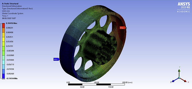
With the fixed support, the compressive force and the force on the gear applied, the stress concentrations and total/directional deformations on the shaft can be determined through solving the static structure in the ANSYS Workbench Software.
The solution of this initial unaltered part provides vital information on how the part can be edited to save weight by highlighting areas of high and low stress under load.

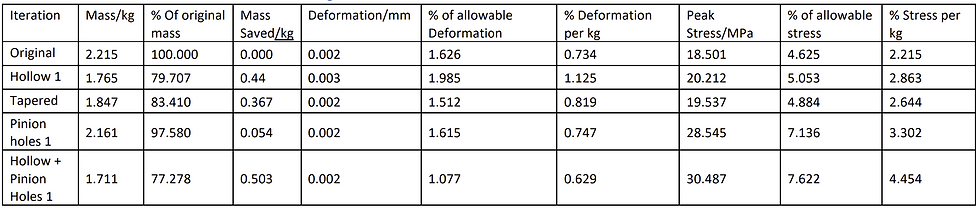
The results of the FEA on the original part show that the percentage of allowable deformation and stress are very low, both at approximately 4%.
This shows that there is large scope for adjustment to this design to greatly reduce its mass whilst still maintaining its ability to function normally. This will produce a product that is far lighter, more efficient, and optimised for the operation it is required to support.
Iteration
3 concept designs were selected; a spoked gear, drilled holes on the face of the gear, and an I-beam cut out. Finite Element Analysis was conducted on rough initial models of each of these designs to collect data and visualise how they would react under load.

Through the data analysis, the I beam concept was chosen.
From here an iterative design process was enacted on the I-beam concept, and 5 iterations later a final design was deemed optimised

If the application had been, for example, a motorsport or hyper-car transmission where minimising mass is highly important, further fine tuning and iterations would be acceptable. The topography feature within ANSYS Workbench could have been used in such an instance where billet CNC machining would be used to see exactly where material could be added or removed to optimise the part to its absolute potential.
Due to the fact that this part is being used within a winch, a compromise to minimise cost and retain ease of manufacture at the expense of absolute maximum weight saving has been made.
Despite this compromise, the part is 30.9% of its mass prior to optimisation, which for this application is a highly significant improvement.


The original shaft showed to have a very low peak stress of 18.5MPa and allowable deformation of 1.63%.
Keeping the limits in mind this original result provided a very good base line to improve the component from. These values allow for the shaft component to be further designed with a much lighter mass in mind whilst maintaining the overall strength.
Ease of manufacturing, efficiency, and optimisation for the use of the component were kept in mind with the following step by step design processes

Iteration
3 concept designs were selected; a straight cut hollow shaft, a tapered hollow shaft with increasing thickness towards the middle, in order to increase cross sectional area at the area of highest bending moment, and a model with holes drilled into the pinion.
The straight cut hole and pinion holes were combined in a fourth design as the they exhibited the most efficient mass saving results. Finite Element Analysis was conducted on rough initial models of each of these designs to collect data and visualise how they would react under load.
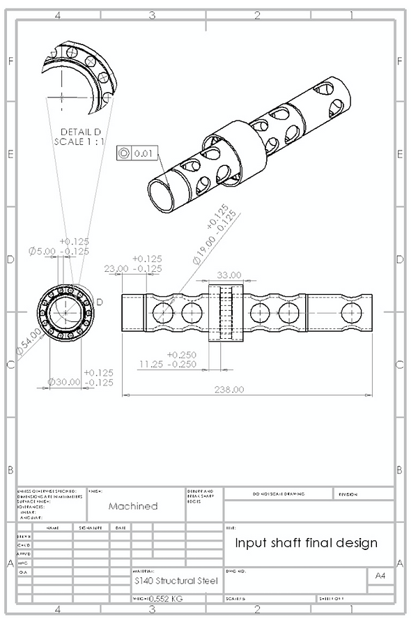
Through the data analysis, the Hollow + Pinion Holes concept was chosen.
From here an iterative design process was enacted on the concept, and 5 iterations later a final design was deemed optimised

This iteration results in significant weight reduction and remains below the allowable deformation and stress.
The overall mass of the shaft has been substantially reduced by roughly 75%, which equates to 1.66kg saved from an initial mass of 2.22kg. Furthermore, the peak stress that the shaft would experience has dramatically increased to 337.42MPa. This is roughly 84% of the allowable peak stress of 400MPa.
The % deformation per kg that the part undergoes has also increased significantly, however the limiting factor of further mass reduction remains as the peak stress.
Identified Flaw
Although this design reduces the weight and pushes the shaft close to its maximum allowable stress, there is a flaw within the design.
One limiting factor to this design is how the shaft would be manufactured. With holes and fillets throughout the component, the manufacturing time and effort would significantly increase rather than just having a hollow shaft
Adding fillets on the extruded holes through the surface area would most likely create lower stress concentration in that area. However, the fillet will not be removed in order to exclude the extra unnecessary manufacturing process. On top of this the 5mm holes that are drilled into the pinion face would need a lot of precision due to the sizing and positioning of the holes. Stopping the alterations at stress 337.42MPa allows for any tolerances or errors that the shaft could experience in certain circumstances to be considered.
Shaft Specific
It was assumed that the section made on SpaceClaim for the pinion was equal to the circumference divided by the number of teeth as mentioned previously. This creates a split of 9mm which simulates the area of a single tooth.